Alexei Ryshkov is a developer of BSL Box V9.3 adapter for CombiLoader.
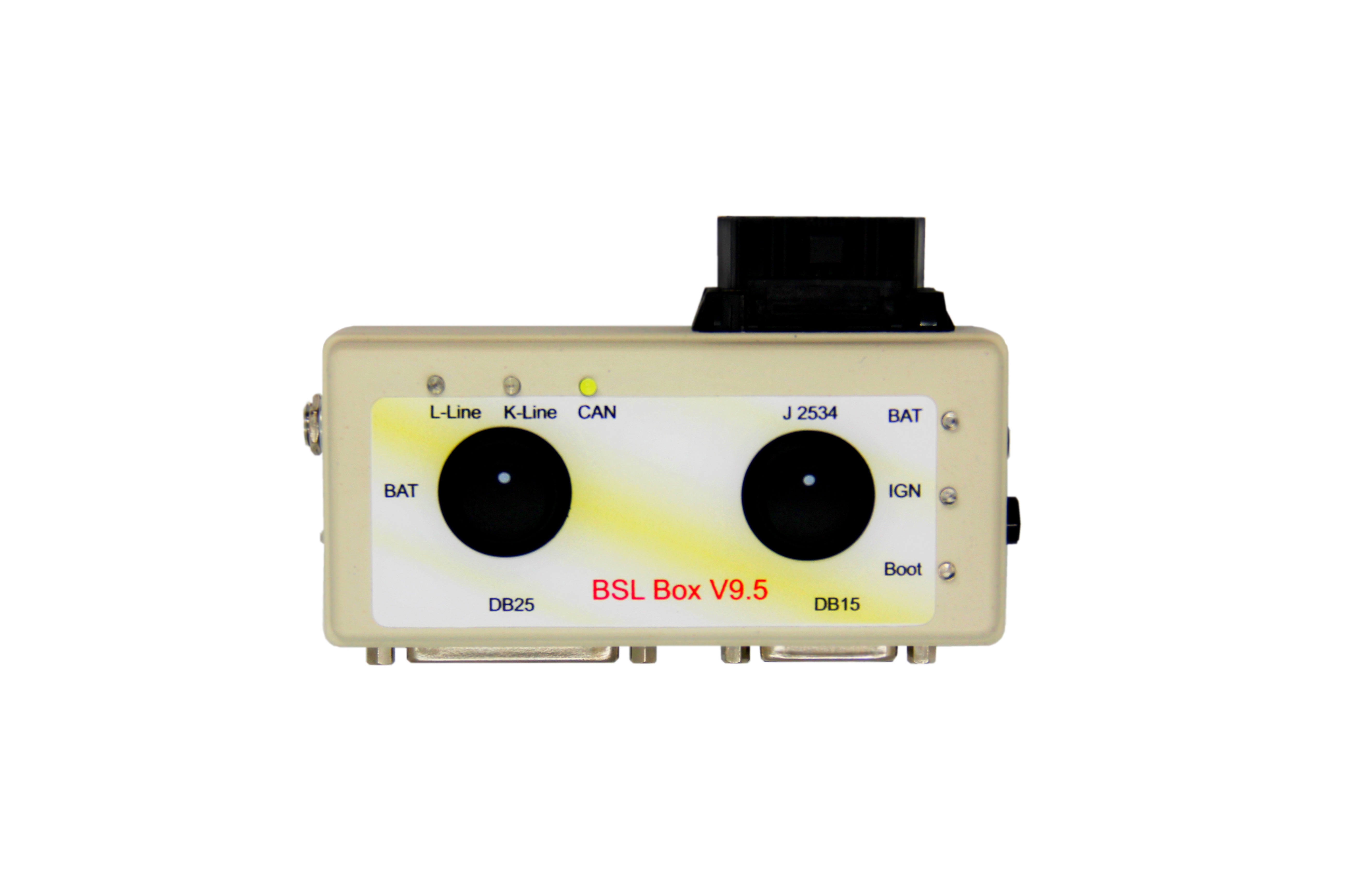 BSL Box V9.5
BSL Box V9.5 is a PCMflash (module 53 and 71), BitBox and MDflasher adapter.
Connecting:
Сonnect the Scanmatik 2 PRO, Tactrix Openport 2.0 adapter via OBD II to BSL Box V9.3
5.5*2.1 12V/3A connector is used for the power supply connection, with the protection against polarity reversal and current overload turned on.
The connection to the ECU is done via DB15 or DB25 with the use of the universal or specialised cable. Simultaneous connection of 2 universal or specialised cables is also possible.
The BSL Box V9.3 adapter allows changing the power supply connected to the 30 and 15 terminals manually. The switches on the right side are the following:
BSL Box V9.5 Adapter displays the status of K-Line, L–Line and CAN signal lines with LED indicators (which is very convenient). There also is a 120 Ohm terminating resistor installed for CAN.
The pins to connect to the ECU
DB25:
1. K-Line
2. GPT1(Scanmatik 2/PCMflash)
4. GPT2(Scanmatik 2/PCMflash)
5. +12 after IGN (K15)
17. +12V (K30)
19. 19. CAN-L 14 pin OBD2
20. 20. CAN-H 6 pin OBD2
22. GND
DB15:
1. Boot 1 (1kOhm)
2. VPP
3. GPT2(Scanmatik 2/PCMflash)
4. CNF (1kOhm)
5. +12 (K30)
7. CAN-H
9. +12 after IGN (K15)
10. Boot 2 (1kOhm)
11. GND
12. GPT1(Scanmatik 2/PCMflash)
14. K-Line
15. CAN-L
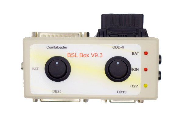 BSL Box V9.3
BSL Box V9.3 is a CombiLoader adapter for Bosch EDC16 BSM (J2534) and Bosch MEDC17 BSM (J2534) modules as well as other modules that work in BSL or on the bench.
Connecting:
First, you need to connect the CombiLoader adapter via DB25 connector and the J2534 device Dialink via OBD2 to BSL Box V9.3
5.5*2.1 12V/3A connector is used for the power supply connection, with the protection against polarity reversal and current overload on. The connection to the ECU is done via DB15 or DB25 with the use of the universal or specialised cable. Simultaneous connection of 2 universal or specialised cables is also possible.
The BSL Box V9.3 adapter allows changing the power supply connected to the 30 and 15 terminals manually. The switches on the right side control the voltage supply of the J2534 Dialink 6V / 12V (depending on the ECU), the second one connects a 120 Ohm resistor to the CAN bus.
The LED indicators indicate the presence of the voltage supply for terminals 15 and 30, as well as 12V J2534 Dialink supply.
The pins to connect to the ECU:
DB25:
1. K-Line (the first pin of the CombiLoader adapter)
2. GPT1
4. GPT2
5. +12 after IGN (K15)
11. PRG
15. Power after main relay (К30Р)
16. Main Relay
17. +12V (K30)
19. CAN-L 14 pin OBD2
20. CAN-H 6 pin OBD2
22. GND
DB15:
3. GPT2
5. +12 after IGN (K15)
7. CAN-H
9. +12V (K30)
11. GND
12. GPT1
14. K-Line (the first pin of the CombiLoader adapter)
15. CAN-L