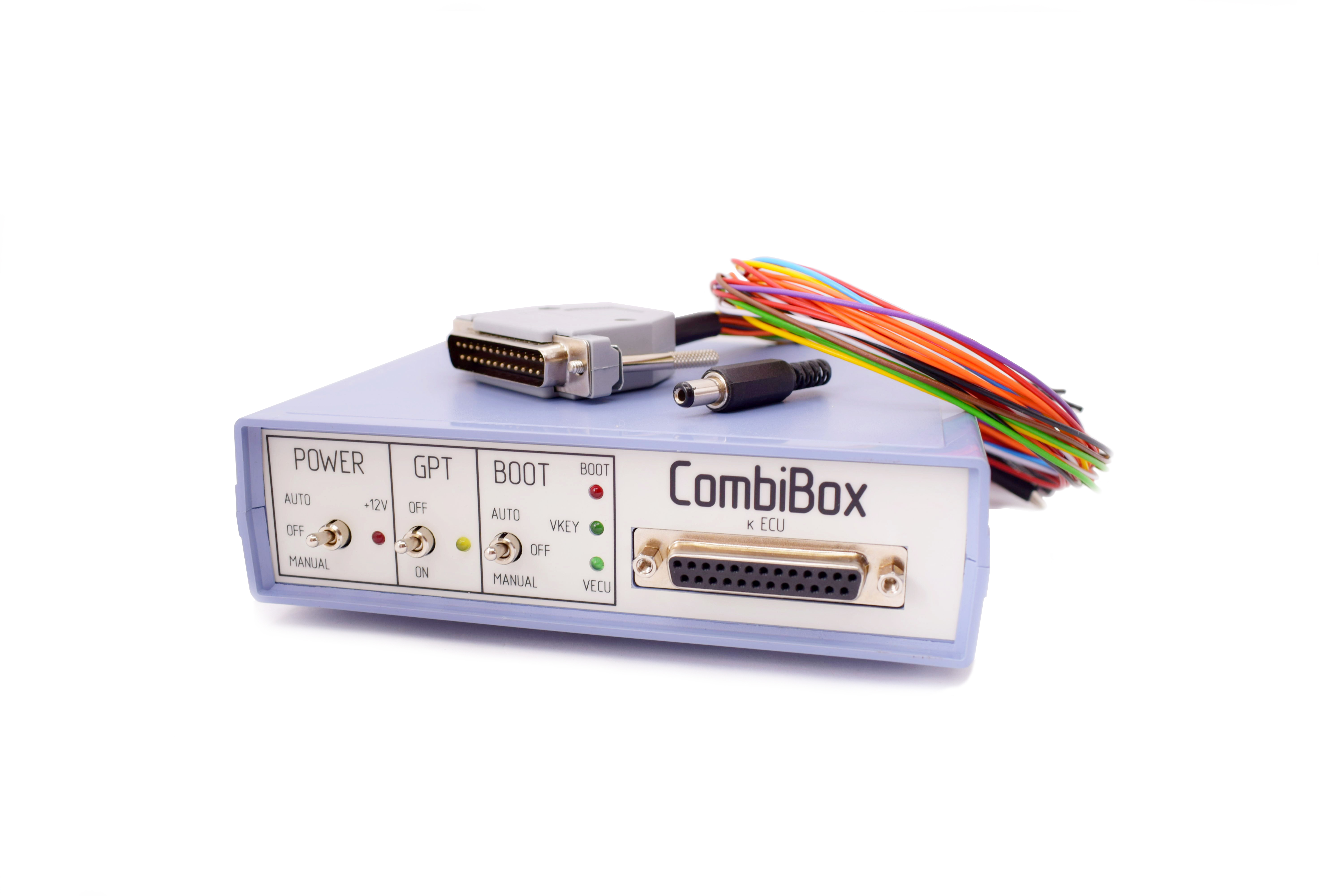
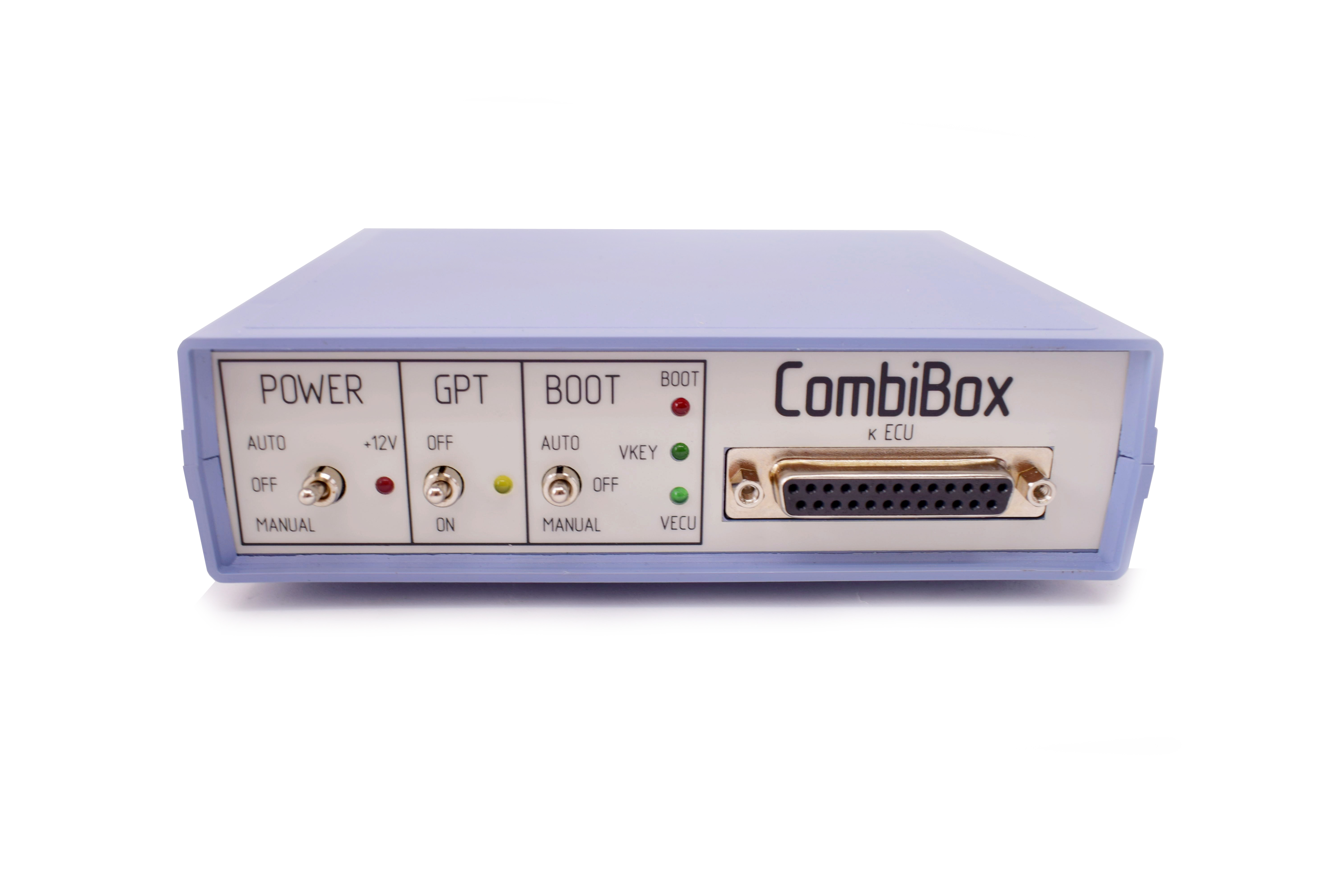
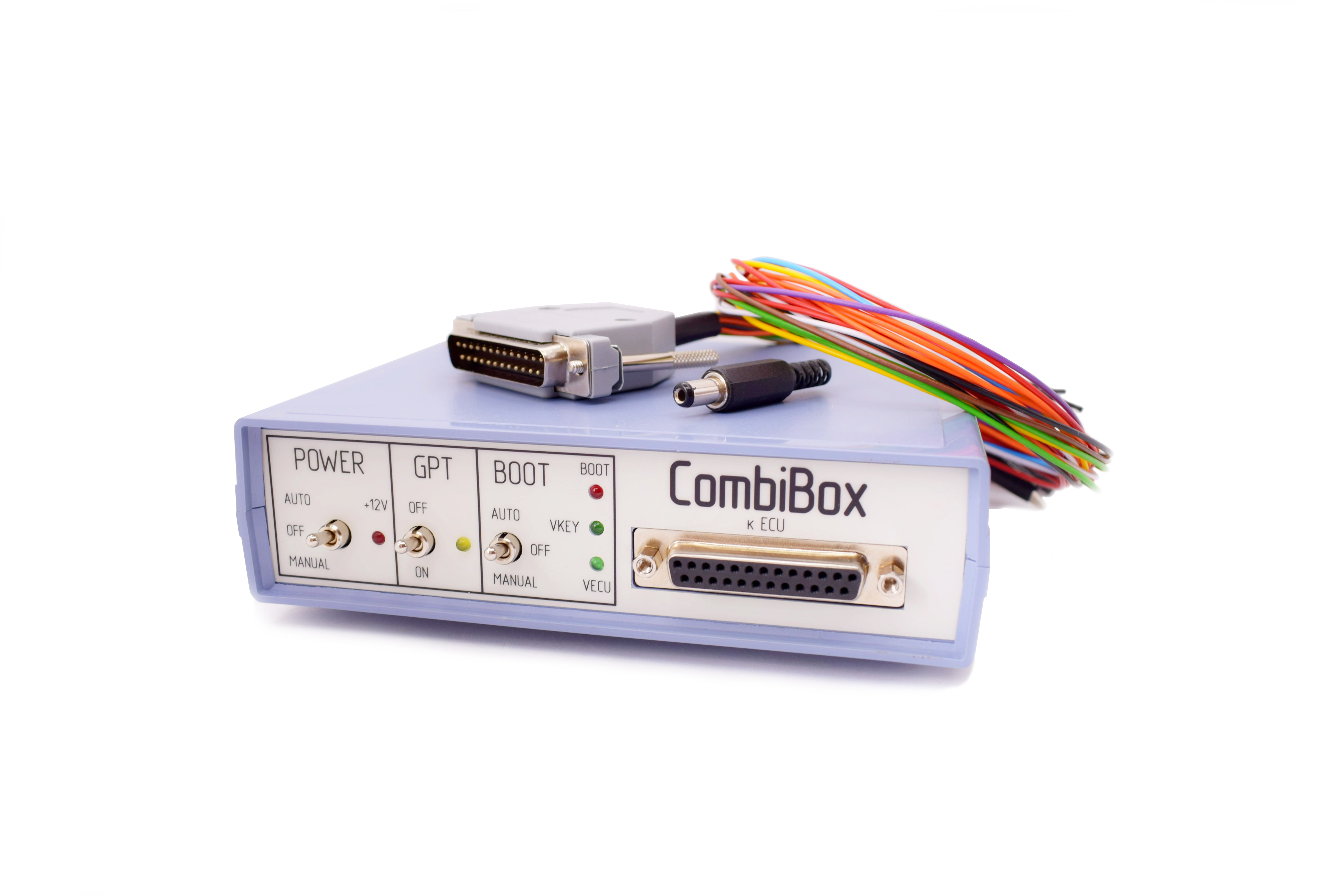
CombiBox is designed to connect an ECU to Combiloader and DIALink adapter on the bench and to switch power and GPT1, GPT2 signals, and to form BOOT, CNF1 signals.
Power
CombiBox requires constant 12V supply voltage. The mating part of the connector is included in the delivery package. It is utterly important to respect polarities when arranging soldered connections of the power cable. Incorrect power supply is EXTREMELY DANGEROUS and may cause the CombiBox or the control unit connected to it to fail. It is recommended to use regulated laboratory power supplies with voltage adjustment range up to 30V and with a maximum current of not less than 3A to safely operate CombiBox and program ECUs.
Connection
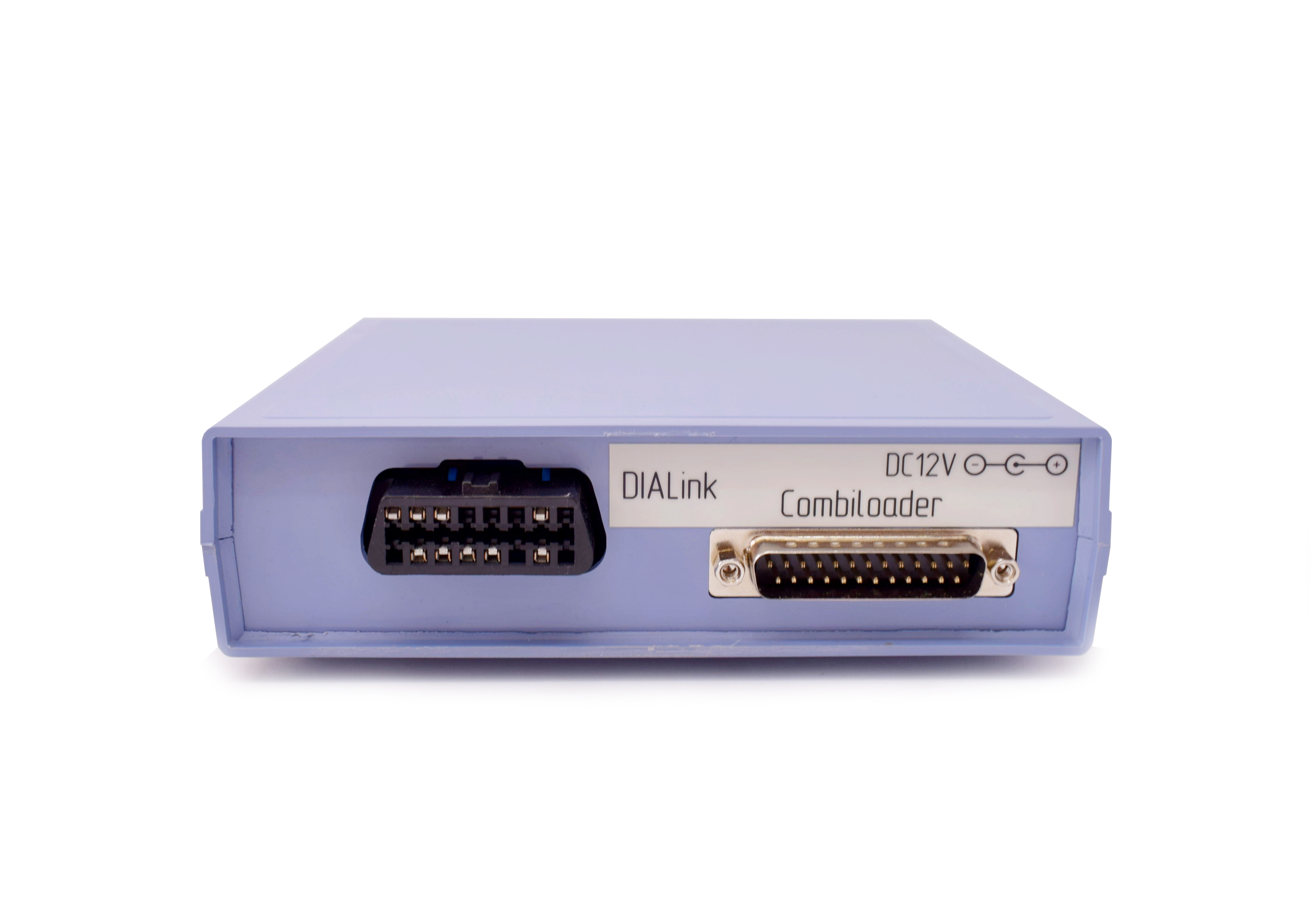
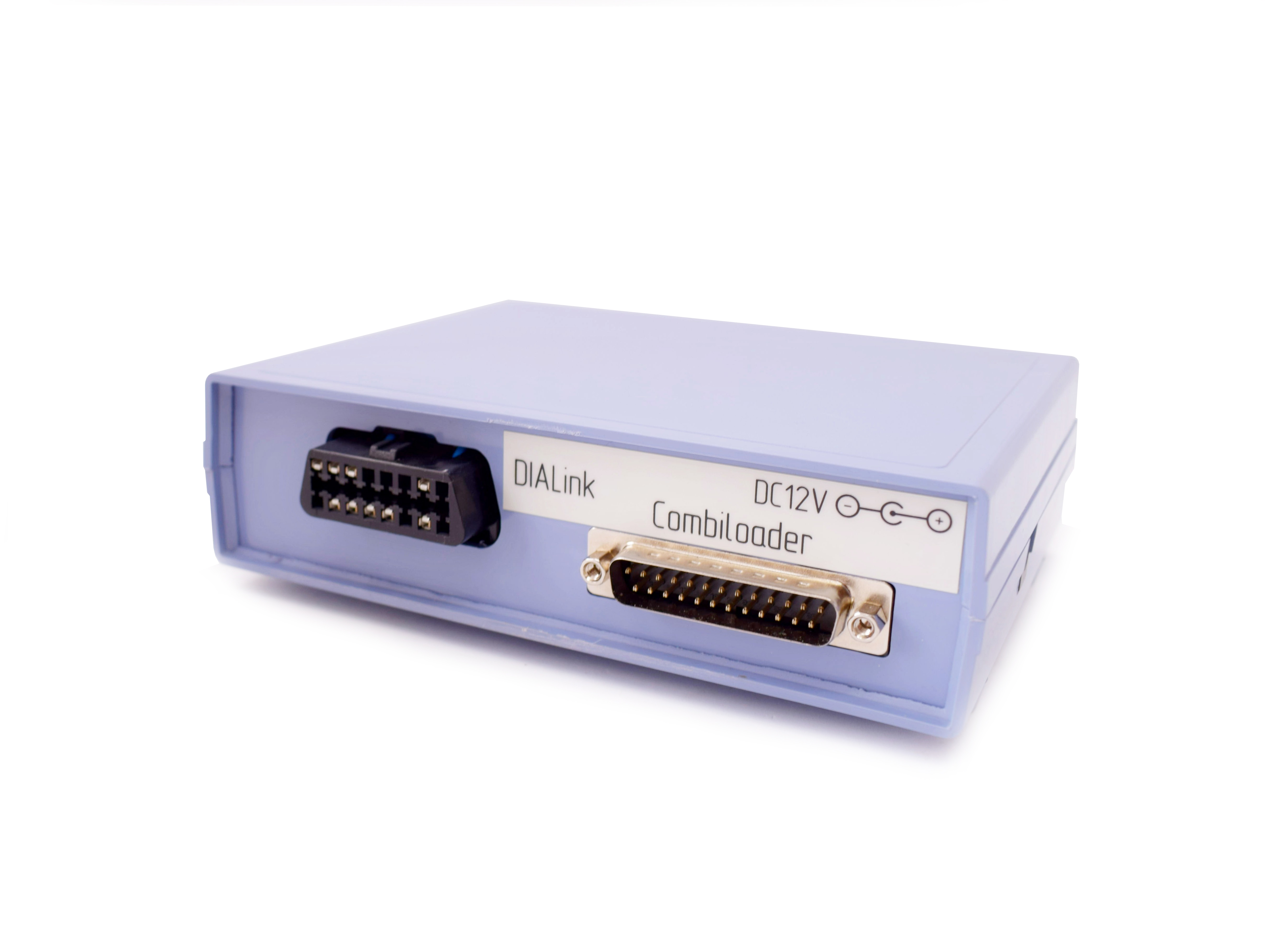
On the back of the CombiBox there are 2 plugs:
1. DIALink is a plug for connecting the adapter of the same name.
The plug has the following connection diagram:
2. Combiloader is a plug for connecting the adapter of the same name.
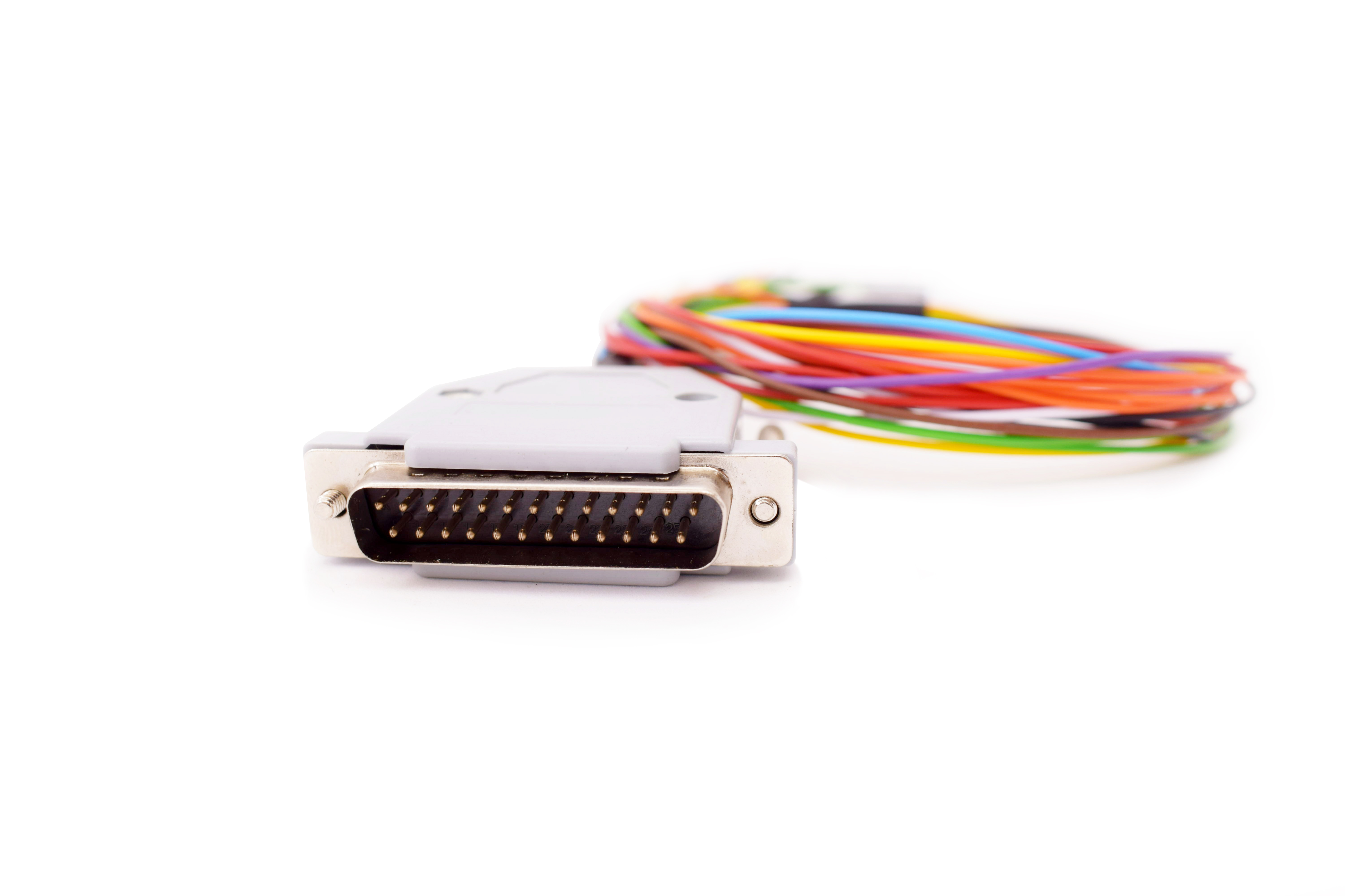
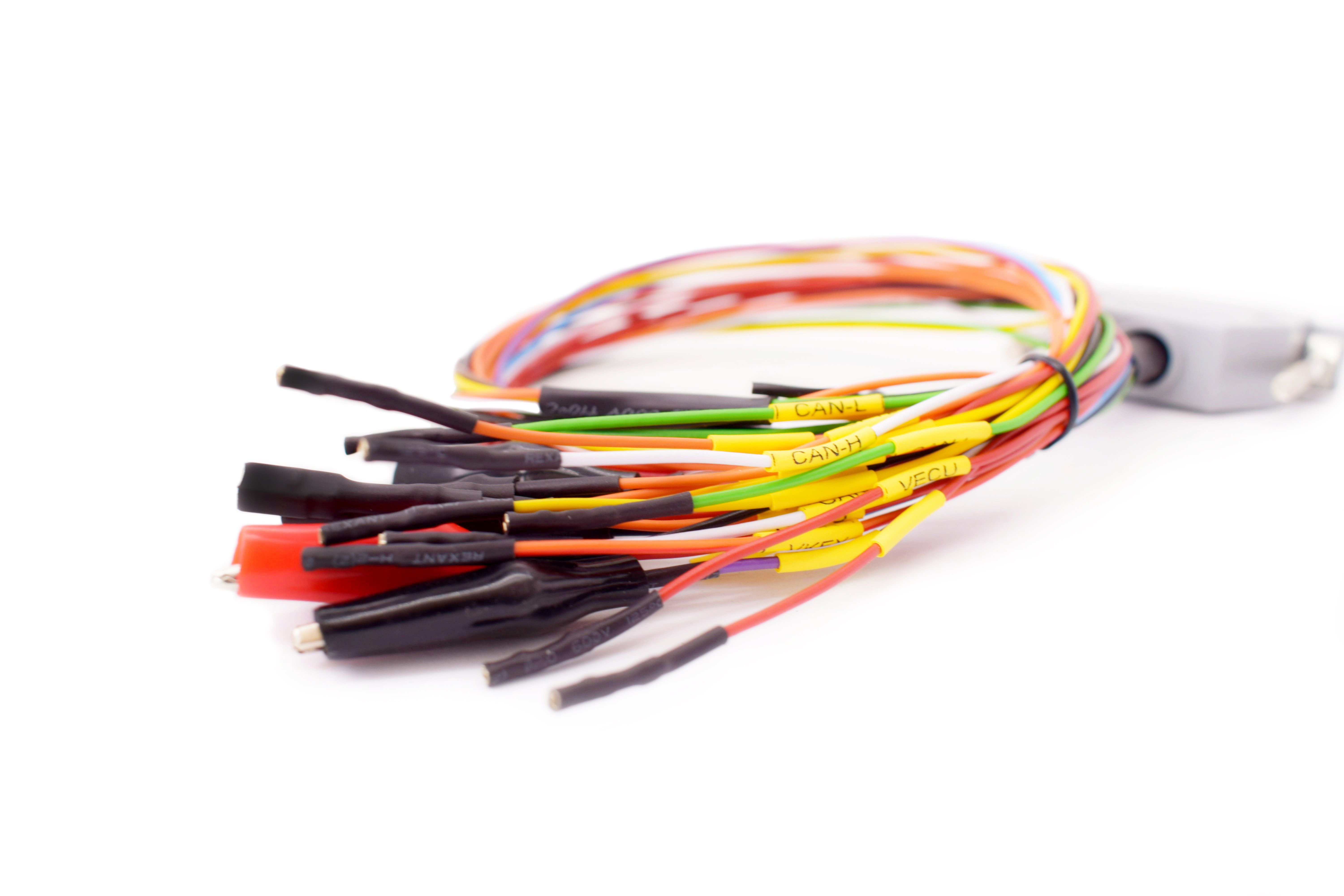
On the front panel of the device there is a DB-25 plug designed to connect to the ECU using the universal cable included in the delivery package. All cable wires are labeled for proper connection. The cable is equipped with additional contact pairs on the «VECU» and «VKEY» circuits, which allows to supply up to eight supply voltages (four small contacts and four large ones).
GPT1 and GPT2 lines are output in a separate bundle along with additional CAN-H and CAN-L.
Control elements
GPT switch
When this mode is activated, signal lines 7 and 15 of the DiaLink plug are switched to the DB-25 plug (GPT1 and GPT2), and power is switched off the DiaLink plug at the same time. It is used for reading a password in the GPT mode. When off, signal lines 7 and 15 are switched to the DB-25 plug (K-line and L-line), and the GPT1 and GPT2 lines are de-energized.
POWER switch, power control
The device has three modes of power supply to the ECU:
BOOT switch, simultaneous control of BOOT and CNF1 signals (3.3V):
The device has built-in current limiting resistors on the signal lines:
Indicators:

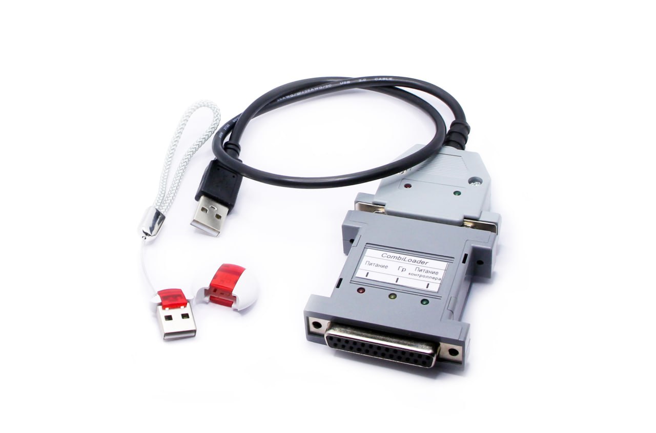 CombiLoader
CombiLoader v.3 is a software and hardware system for reading and writing FLASH and EEPROM in the ECUs installed in various vehicles. It provides writing of the map area without dismantling an ECU from the vehicle by means of the diagnostic writing method for all the ECUs when possible. The flasher is convenient to work with, reliable and has a number of additional functions. It is regularly updated and provided with technical support. Combiloader is the most popular chip tuning software in Russia.
Please note: The software interface has been translated into English though some modules are still in Russian only. Help section is available only in the Russian language.
NB: Please always provide the correct email the tool is registred with. Activation may not be possible if the email is incorrect. If you resell your tool, please contact the developer or us via email for the reregistration and provide the new name, surname and email address of the end user.
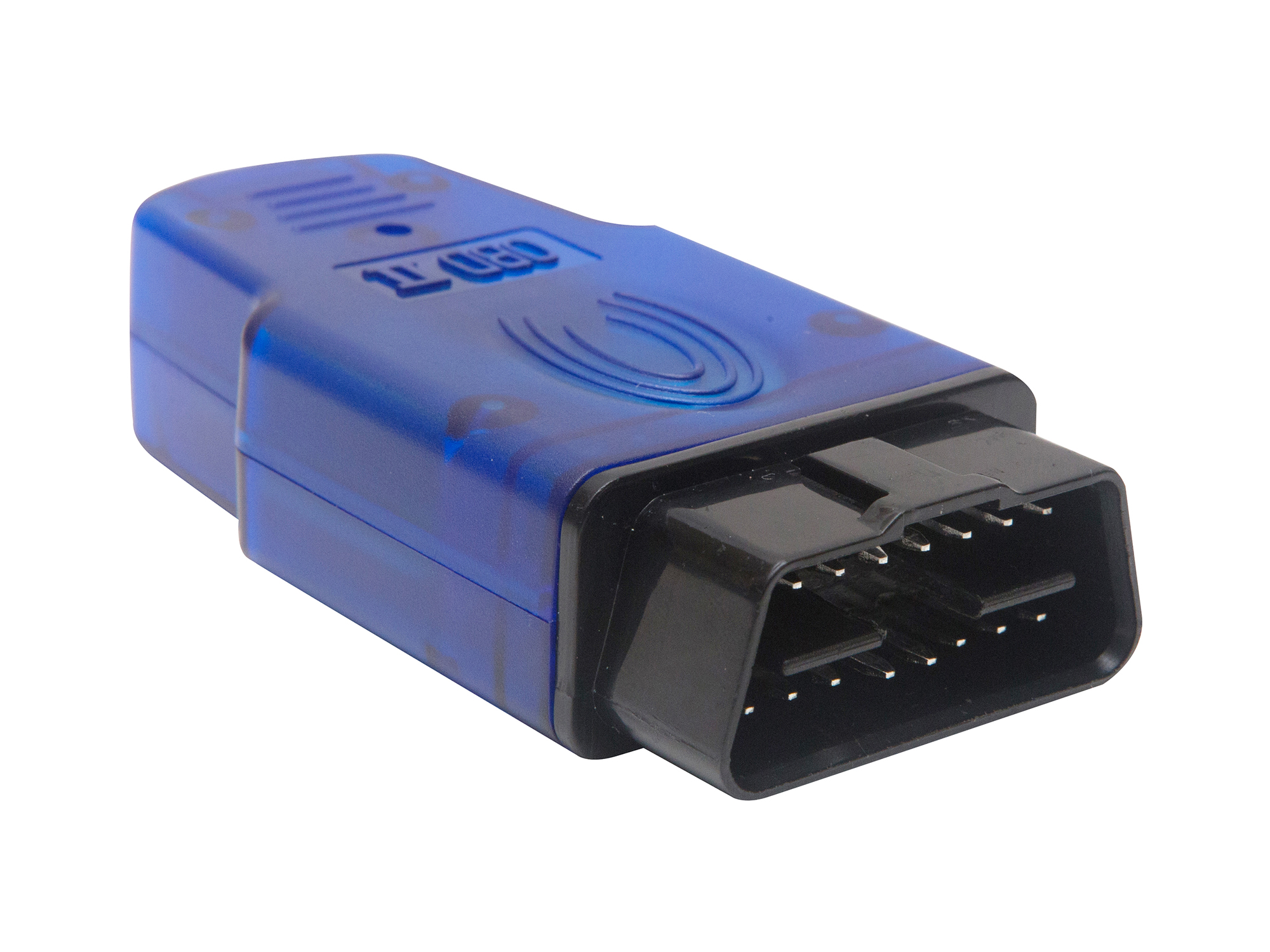 Dialink
The universal J2534 Dialink adapter by SMS-Software is designed for ECU diagnostics and reprogramming via CAN-bus, it is fully compatible with Combiloader and can be used with any third-party software.
Dialink application:
Advantages:
*1 in comparison with OpenPort software.
*2 the exchange speed of ISO-11898 (CAN) reaches the max capacity of the bus. It is up to 8 times faster than OpenPort operational speed.
Supported protocols:
Power:
The full operational range of power voltage is from 8V to 35V which guarantees fail-free operation in any working conditions including trucks.
PC (laptop) connection:
Diagnostic connector pins:
Extra features:
Thanks to the built-in microprocessor DiaLink adapter can be used not only as a diagnostic adapter for SMS-Diagnostics 3 software or as a J2534 compatible device but also can be configured for use in the following modes