Gruzdev
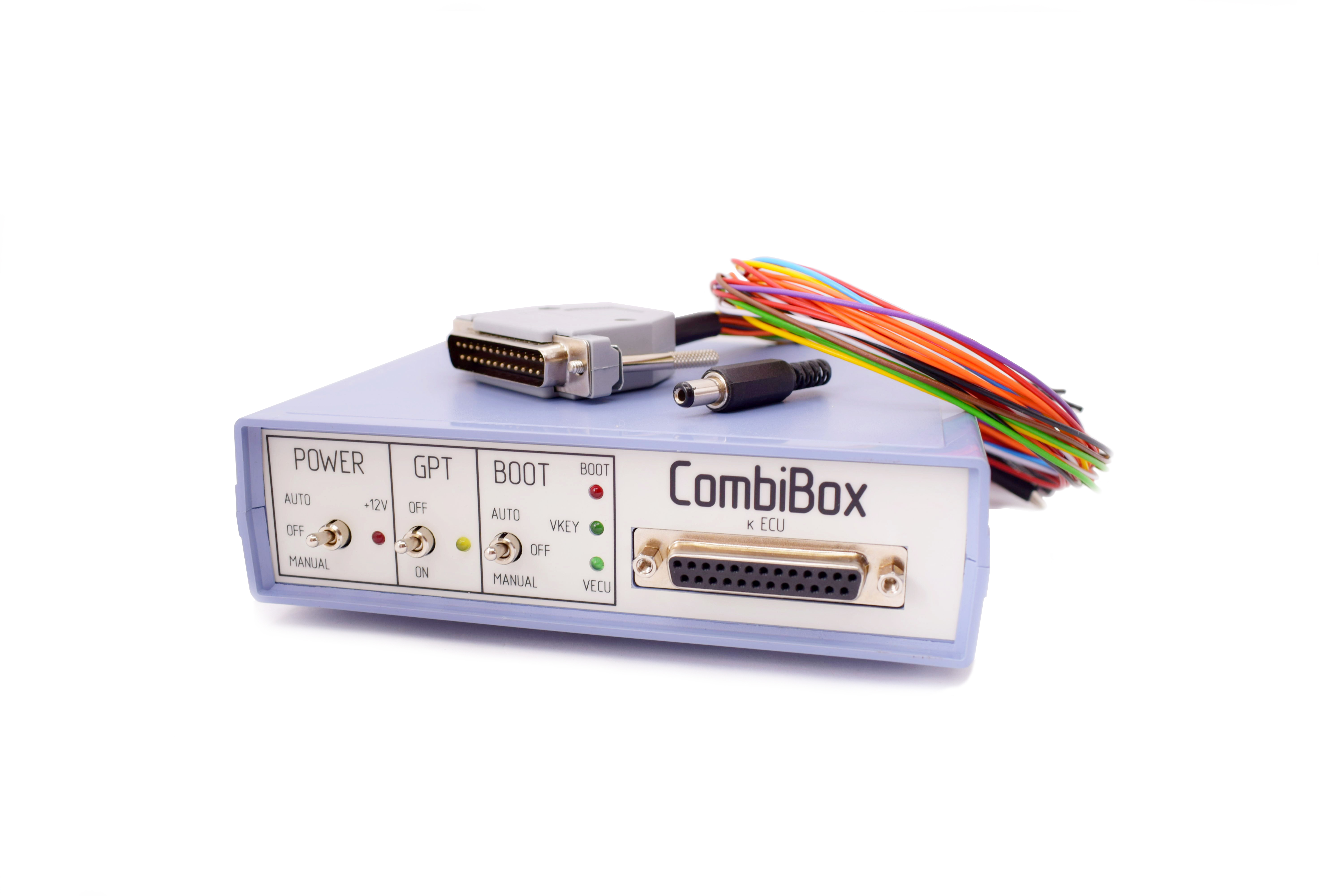 CombiBox for Combiloader
CombiBox is designed to connect an ECU to Combiloader and DIALink adapter on the bench and to switch power and GPT1, GPT2 signals, and to form BOOT, CNF1 signals.
Power
CombiBox requires constant 12V supply voltage. The mating part of the connector is included in the delivery package. It is utterly important to respect polarities when arranging soldered connections of the power cable. Incorrect power supply is EXTREMELY DANGEROUS and may cause the CombiBox or the control unit connected to it to fail. It is recommended to use regulated laboratory power supplies with voltage adjustment range up to 30V and with a maximum current of not less than 3A to safely operate CombiBox and program ECUs.
Connection
On the back of the CombiBox there are 2 plugs:
1. DIALink is a plug for connecting the adapter of the same name.
The plug has the following connection diagram:
2. Combiloader is a plug for connecting the adapter of the same name.
On the front panel of the device there is a DB-25 plug designed to connect to the ECU using the universal cable included in the delivery package. All cable wires are labeled for proper connection. The cable is equipped with additional contact pairs on the «VECU» and «VKEY» circuits, which allows to supply up to eight supply voltages (four small contacts and four large ones).
GPT1 and GPT2 lines are output in a separate bundle along with additional CAN-H and CAN-L.
Control elements
GPT switch
When this mode is activated, signal lines 7 and 15 of the DiaLink plug are switched to the DB-25 plug (GPT1 and GPT2), and power is switched off the DiaLink plug at the same time. It is used for reading a password in the GPT mode. When off, signal lines 7 and 15 are switched to the DB-25 plug (K-line and L-line), and the GPT1 and GPT2 lines are de-energized.
POWER switch, power control
The device has three modes of power supply to the ECU:
BOOT switch, simultaneous control of BOOT and CNF1 signals (3.3V):
The device has built-in current limiting resistors on the signal lines:
Indicators:
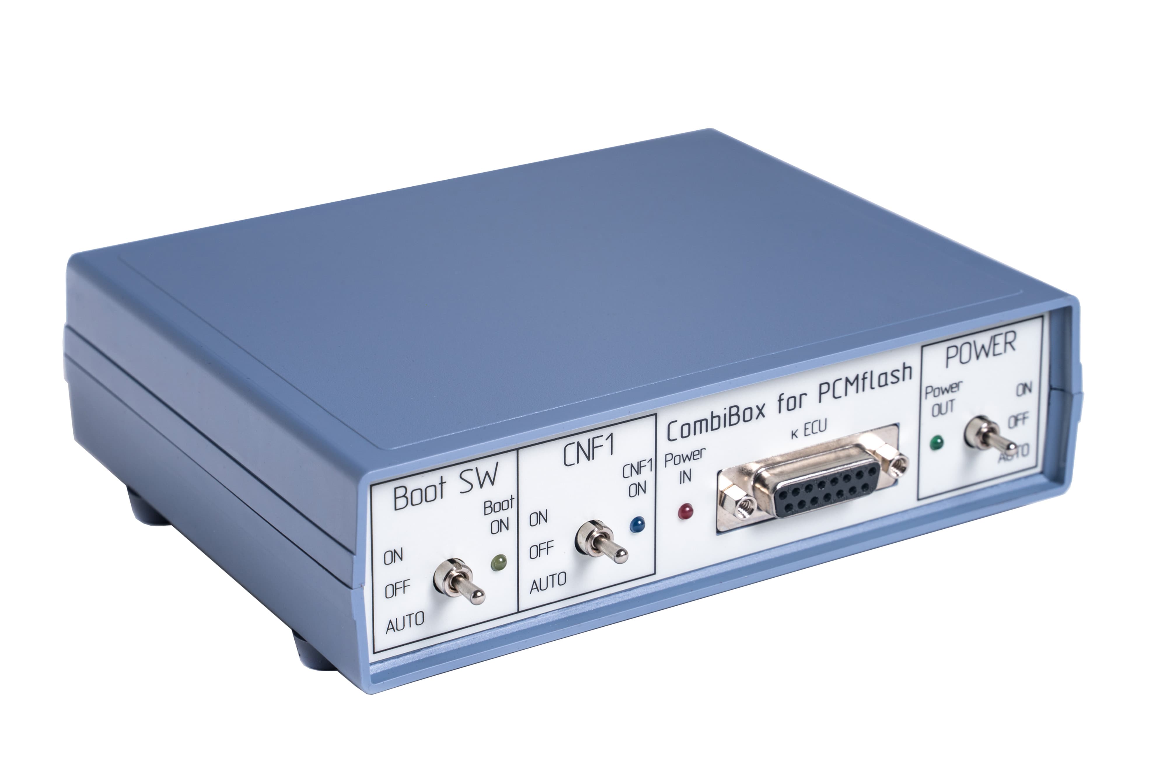 CombiBox for PCMflash
CombiBox is designed to connect an ECU to PCMflash and a J2534 device on the bench and to switch power and GPT1, GPT2 signals, and to form BOOT, CNF1 signals. When used with Scanmatik 2 PRO CombiBox for PCMflash allows to form GPT1, GPT2 signals necessary to work with Module 53 and Module 71, and future modules.
Power
CombiBox requires constant 12V supply voltage. The mating part of the connector is included in the delivery package. It is utterly important to respect polarities when arranging soldered connections of the power cable. Incorrect power supply is EXTREMELY DANGEROUS and may cause the CombiBox or the control unit connected to it to fail. It is recommended to use regulated laboratory power supplies with voltage adjustment range up to 30V and with a maximum current of not less than 3A to safely operate CombiBox and program ECUs.
Connection
On the back of the CombiBox there are 2 plugs:
1. J2534 is a plug for connecting a J2534 device (Scanmatik 2 PRO).
The plug has the following connection diagram:
2. DC IN 5A Max Jack is a plug for connecting power supply.
On the front panel of the device there is a DB-15 plug designed to connect to the ECU using a universal cable. All cable wires have appropriate markings to connect them correctly.
The plug has the following connection diagram:
Controls elements
«POWER» switch, power control. The device has three modes of power supply to the ECU:
Boot SW switch, BOOT signal control:
«CNF1» switch, CNF1 signal control (3.3V):
The device has built-in current-limiting resistors on signal lines:
Indicators:
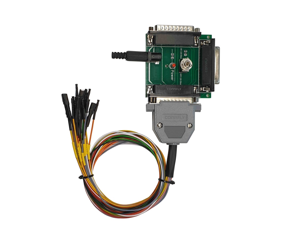 Universal cable for Combiloader + Scanmatik
Universal cable for connecting and programming the ECU on the bench using Combiloader and Scanmatic SM2/SM2PRO adapter. It is also intended for use with integrated modules such as Bosch MEDC17 BSM, Bosch EDC16 BSM and Bosch ME9 BSM module kit and Module kit: SIMOS12/18 VAG (J2534).
Connects directly to the SM2/SM2PRO adapter. The following outputs of GPT signals must be specified in the Combiloader settings.
OBDII Pin SM2/SM2Pro Pin DB25 SM2/SM2Pro
Signal
1 23 GPT1
2 4 GPT2
The universal cable has the ability to connect a 120 Ohm terminating resistor on the CAN-bus.